Electrical Distribution Systems for Electrical Contractor Exam
Understanding how electricity is transmitted is vital to answering many questions on the electrical contractor's test. Let's examine this, transfer process in more detail through the images below, it shows a generic distribution system.
- power source (where electricity is actually made).
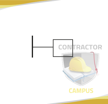
- power source connects to a secondary transmission system
- the secondary transmission system connects to substations
- substations in term connect to primary distribution systems
- the primary distribution system in term connects to the main laterals, which connect to distribution transformers
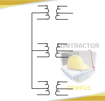
- from these distribution transformers service mains one connected.
Now that we're gone through this electrical transfer process step-by-step, let's put it together
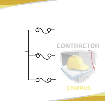
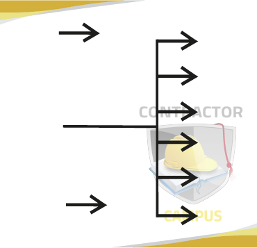
Please note that the image alone represents what is known or a radical distribution system. There is another electrical distribution arrangement know or the ring main distribution system, the diagram below shows the said system.
Notice that the arrangement of components in the ring main system seems preferable from a maintenance perspective. If a section of the system needs repairs or goes down for any reason it does not affect the rest of the system. On the other hand, in a radical system, everything "often" the affected area goes down as well.
Substations, feeders, distributions, and transformers
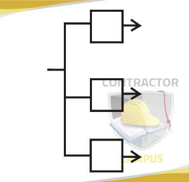
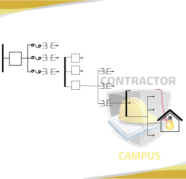
Before diving into the difference between feeders and distributors, less remember that electric power is distributed through a network of components like distribution substations primary distribution feeders, distribution transformers, distributors and service mains.
| Substation | Primary Distribution Feeder | Distribution Transformers |
|---|---|---|
| electrical power gets stepped-down at a Substation ⇒ |
the Primary distribution feeder feeds the distribution transformer ⇒ |
After being stepped-down electrical power goes to the distribution transformers theory the primary distribution feeders ⇒ |
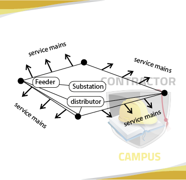
Notice for the diagram above that the key difference between feeders and distributors is that feeders transfer power from one place to another without being drained or connected to anything else. What gets put into a feeder is equal to what it puts out.
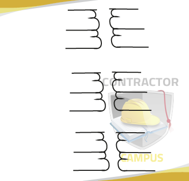
DC Distribution
2-Wire
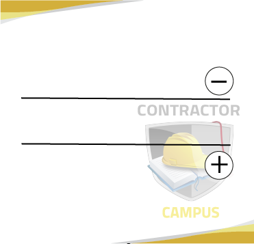
In a 2 wire system, one wire is negative and the other is negative.
3-Wire (Single-Phase)
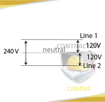
Three-wire systems have a "middle" neutral line (absent in 2-wire systems). This neutral line is grounded and the voltage between it and any of the two outer lines is holy as much or that between the two outer lines.
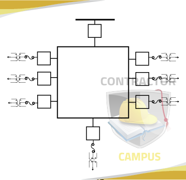
Three-phase service Distribution Systems
Four Wire Wye
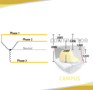
Notice that voltage between "phase wires" is 208V and voltages between only "phase wire" and neutral is 120V.
Three Wire Delta
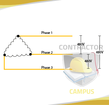
Notice there is no neutral (that's the key difference between wye and delta). Also, notice the voltage is the same between any two phase wires.
Four Wire Delta (High Leg)
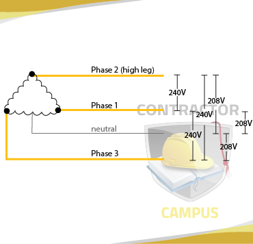
Notice that the four-wire delta gets its fourth wire from looking an to the middle of a transformer windings.
Doing so creates a neutral for 120V single-phase loads.