1-Phase vs 3-Phase Power
It is important to know the difference between single-phase and 3-phase power. Most contractors can make it through their exam without truely understanding the theoretical difference (most if not all electricians do know the practical differences). Since some questions explicitly target your knowledge of the theoretical difference between 1-phase and 3-phase power, we explore the matter in the paragraphs below.
1-Phase Power
Let's imagine a very basic generator.
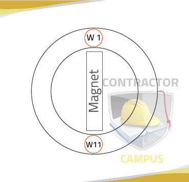
It has a rotating magnet. Recall from basic electromagnetism that as this magnet rotates voltage get induced on the terminals of the windings surrounding the rotating magnet.
Assume we only have two windings, W1 and W11.
When the magnet "posses by" or "points to" W1 and W11, both voltage and current are generated and they are in phase.
If we were to graph both voltage and current we would use that they start, reach their peak and drop to zero at the same time. They are in phase with each other. (see image)
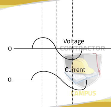
Note that explaining the nature of the graphs (sine wave) is beyond the scope of an electrical contractor's test. We will skip the said explanation.
Recall that power is equal to Voltage times Current
therefore when voltage and current are at their highest, they will produce obtained is zero. If we were to graph the power output of single-phase, the graph would look as follows:
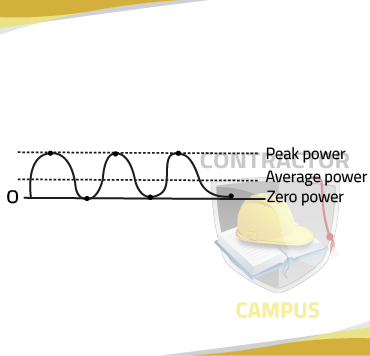
Power output in single-phase
From the graph alone, we know that if power is any value P, then the average power is P/2. Actual proof of how P/2 is mathematically denied is beyond our scope as electrical contractors, but you can intuitively think about it and make sense of it:
if "holy of the time" it is at P and "holy of the time" it is at 0, then the average P + 0 / 2 = P/2.
Thus, we conclude that in single-phase power the average of the power output is ONLY holy of the maximum power.
3-Phase Power
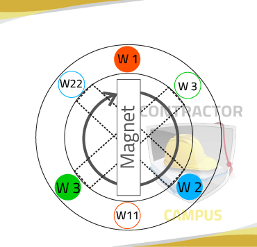
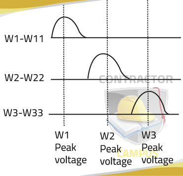
If we add two more sets of windings around our rotating magnet (we now have W1, W2, W3, and their respective opposite), and they are 120° away from each other (see images), as the magnet rotates past W1, W2, and W3, their respective voltage will peak.
If we were to graph their respective voltages, we could see that as one drop, the next one increases.
Although not proven here, the average power output of 3-phase IS 1.5 times higher than peak power and is constant.